1. Distinguish the bearing from its housing
A caged cylindrical-roller bearing has rings, separate cylindrical rolling elements and a cage that keeps the rollers apart. The enclosing housing is a different part of the assembly. SKF's 27 February 2007 article supplies this general vocabulary; its proprietary product design and performance results do not describe our model. SKF Evolution: cylindrical-roller bearing terminology.
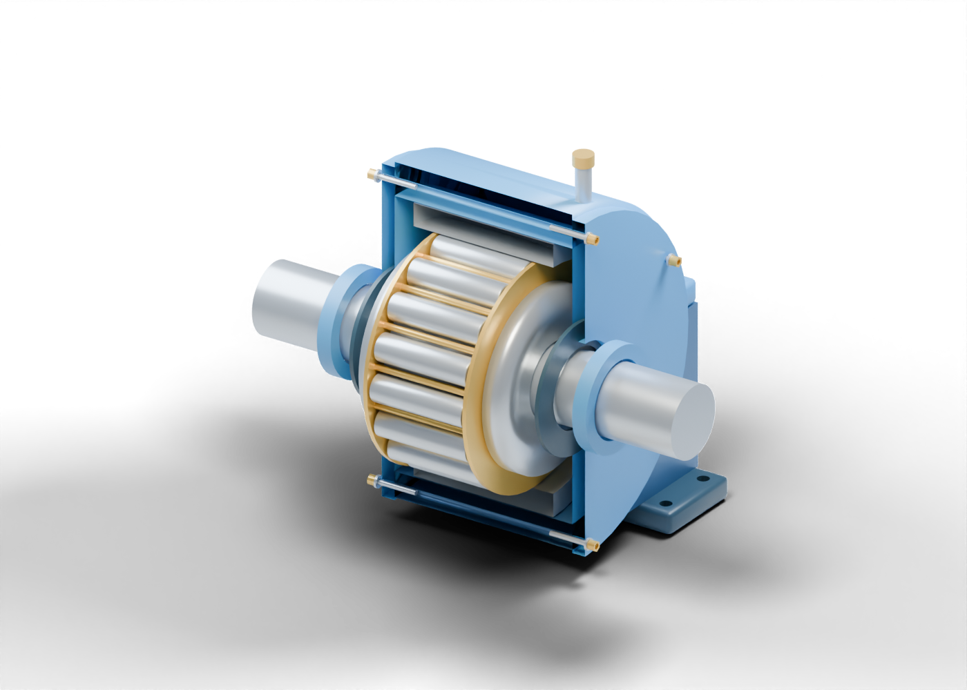
Our independently invented teaching assembly has 99 named mesh instances and twelve component studies. Sixteen silver rollers sit between two hollow bearing rings, surrounded by a blue split housing. A solid shaft, gold cage regions, end covers and independent connection markers make different roles inspectable. These pieces do not establish a catalogue bearing type or an installation in an identified Alberta plant.
2. Read the rings, rollers and deliberate gaps
The inner ring has a hollow bore around the shaft, a lower central track and raised end regions. The outer ring provides a separate surrounding race region. Each roller has rounded ends and its own selectable name. The sixteen roller instances share one original mesh; they are repeated members of this assembly, rather than sixteen distinct bearing designs.
Visible spaces distinguish the shaft from the ring bore and the rollers from the invented race regions. These are deliberate teaching gaps. They are not selected running clearances, an interference fit, a demonstrated load path or calculated rolling contact. The model stays static: orbiting the view moves the camera, not the bearing through a mechanical cycle.
3. Separate spacing, enclosure and sealing roles
Gold bridges occupy regions between adjacent rollers, while two annular cage end rings connect the repeated bridge regions. Their windows are real geometric openings. The simple cage shapes explain spacing without reproducing a manufacturer's optimized design, retention method or production construction.
The blue upper cap and lower support housing surround the bearing. Two annular covers have shaft openings and separately drilled joint locations. Dark annular markers locate seal regions but provide no lip, labyrinth, compound or leakage result. A hollow lubrication neck passes through the cap beside the bearing and ends at a closed fitting marker; it supplies no grease-delivery event.
The still hides the facing halves, associated hardware and foot to show internal parts; the interactive model retains them. The full interactive model retains those parts. Neither the cutaway nor the Separate parts control is an opening or service sequence.
4. Match a visible part to the evidence it supplies
| Original component | What the teaching assembly shows | What requires separate evidence |
|---|---|---|
| Inner and outer rings | Hollow rings and distinct invented race regions | Selected bearing type, fits, clearances, contact stresses and duty |
| Sixteen cylindrical rollers | Individually named static shapes with rounded ends | Actual rolling, traction, loading and service life |
| Cage bridges and end rings | Separate spacing regions, windows and connecting members | Guidance, retention, dynamic forces and manufacturing qualification |
| Split housing and end covers | Open cavities, shaft openings and drilled joint positions | Housing strength, qualified enclosure, joint engagement and preload |
| Seal and lubrication markers | Annular seal locations and an independent hollow connection | Seal performance, lubricant selection, distribution and delivery |
| Support feet | Eight actual drilled positions across two independent feet | Anchorage, foundation, structural loads and installation qualification |
5. Read reliability claims as evidence questions
A reliability headline may mention a lubricant, sensor or bearing replacement. Identify what was changed and what was measured before accepting a claimed result. The date, asset, operating context, comparison period and source of the measurement should be explicit. This guide does not verify a particular intervention or report plant performance.
SKF's 28 June 2013 lubrication article describes lubrication as a dynamic process and distinguishes it from monitoring, including vibration measurements and grease-condition tests. A drawn fitting provides none of those records. We use that distinction as background, without adopting the article's application-specific models, temperatures, grease selection or maintenance instructions. SKF Evolution: lubrication and condition-monitoring concepts.
For this static model, the answer is limited: the hollow neck locates an opening, the closed marker locates a fitting, and no lubricant is delivered or analyzed. No load rating, bearing-life estimate, temperature result, diagnosis or maintenance interval is supplied.
6. Inspect exact components in the original atlas
Open the housed roller bearing for the complete assembly. Inspect the first cylindrical roller, the first cage bridge and the lubrication connection neck as exact named components.
Compare the mechanical face-seal lesson and reciprocating-compressor lesson to distinguish shaft support, sealing and gas compression. These independent concepts have invented proportions and do not establish a compatible set of parts, replacement selection or matched machine installation.