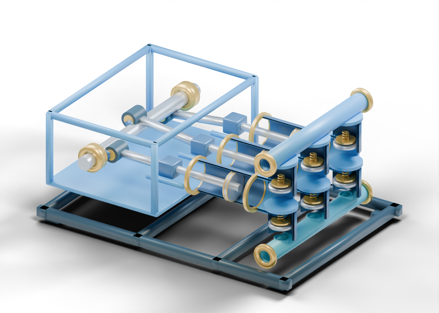
1. Put the pump in the drilling-fluid story
The Alberta Energy Regulator's drilling overview explains why drilling fluid is pumped through a well: it helps manage pressure and carry rock fragments. A triplex pump is a three-unit positive-displacement pump family. Our original 112-part 3D mud-pump cutaway is a way to inspect mechanical roles, not a drawing of a named rig pump. Its dimensions, colors and pose are invented. Start at the common crankshaft and follow one bank before comparing the other two.
2. Trace the power end without pretending it moves
Bank one's offset crank pin sits away from the shaft axis and meets a separate connecting rod. The crosshead and piston rod show the next mechanical relationship. Compare the second and third crank pins; their three positions differ in this single frozen pose. NOV's mud-pump overview identifies power-end and fluid-end roles in real products. No NOV component shape or rating is reproduced here. Static offsets are not a measured timing diagram, balance study, stroke length or load calculation.
3. Look through the liner, then find the fluid end
The first complete liner has a real axial opening in the delivered interactive model, with a separately selectable piston marker inside. The Alberta-blue studio poster removes only the facing shell half after the complete 3D asset is exported, so the relationship can be seen at article size. Select the second liner to compare another bank. The fluid-end chamber is an invented teaching shell, not a pressure-qualified casting. A visible piston and bore cannot establish sealing, displaced volume, pressure or pump capacity.
4. Keep suction and discharge valve questions separate
Within one bank, the lower suction seat and upper discharge seat each have an actual open bore. A separate suction plate and discharge spring mark possible valve-component roles. They do not lift or cycle. The central valve pockets are deliberately open sections; a real pressure boundary would require an engineered junction. The lower suction manifold and upper discharge manifold are distinct open teaching boundaries, not verified flow paths through a complete fluid end.
5. Ask what a real pump claim would need
| Visible cue | Useful question | Evidence still needed |
|---|---|---|
| Three crank banks | What actual drive and operating speed apply? | Equipment data, loading and operating record |
| Hollow liners and pistons | What fluid-end size and condition are installed? | OEM specifications, inspection and maintenance history |
| Suction and discharge seats | How do real valves perform in service? | Valve design, timing, wear and pressure evidence |
| Two open manifolds | Where do the actual connections lead? | Qualified piping, relief, hose and controls |
An illustration cannot validate a mud-pump pressure rating, flow, pulsation, relief system or safe operating procedure. The open valve-pocket gaps are especially important: the cutaway is intentionally incomplete as a fluid-containing assembly.
6. Return to Alberta reporting with sharper questions
Open the complete component explorer and select the named parts alongside a report about drilling performance or service equipment. Ask which pump was used, on what well and date, what fluid and operating conditions applied, and which record supports a claimed outcome. The model provides vocabulary and spatial context; the actual equipment record supplies the result.