1. Put the separator between two distinct lessons
A public Alberta project description gives one example in which wet steam from a once-through steam generator reaches a separator. Upper steam proceeds toward injection handling; lower liquid blowdown goes to further processing. The U.S. Department of Energy steam sourcebook explains the general role of removing entrained water from a steam line. These references support component roles, not our geometry or a universal SAGD arrangement.
Our original 3D separator cutaway sits conceptually after the separate steam-generator cutaway and before the separate injector and producer well-pair scene. Their open ends do not form a connected plant.
2. Follow the inlet into the vessel
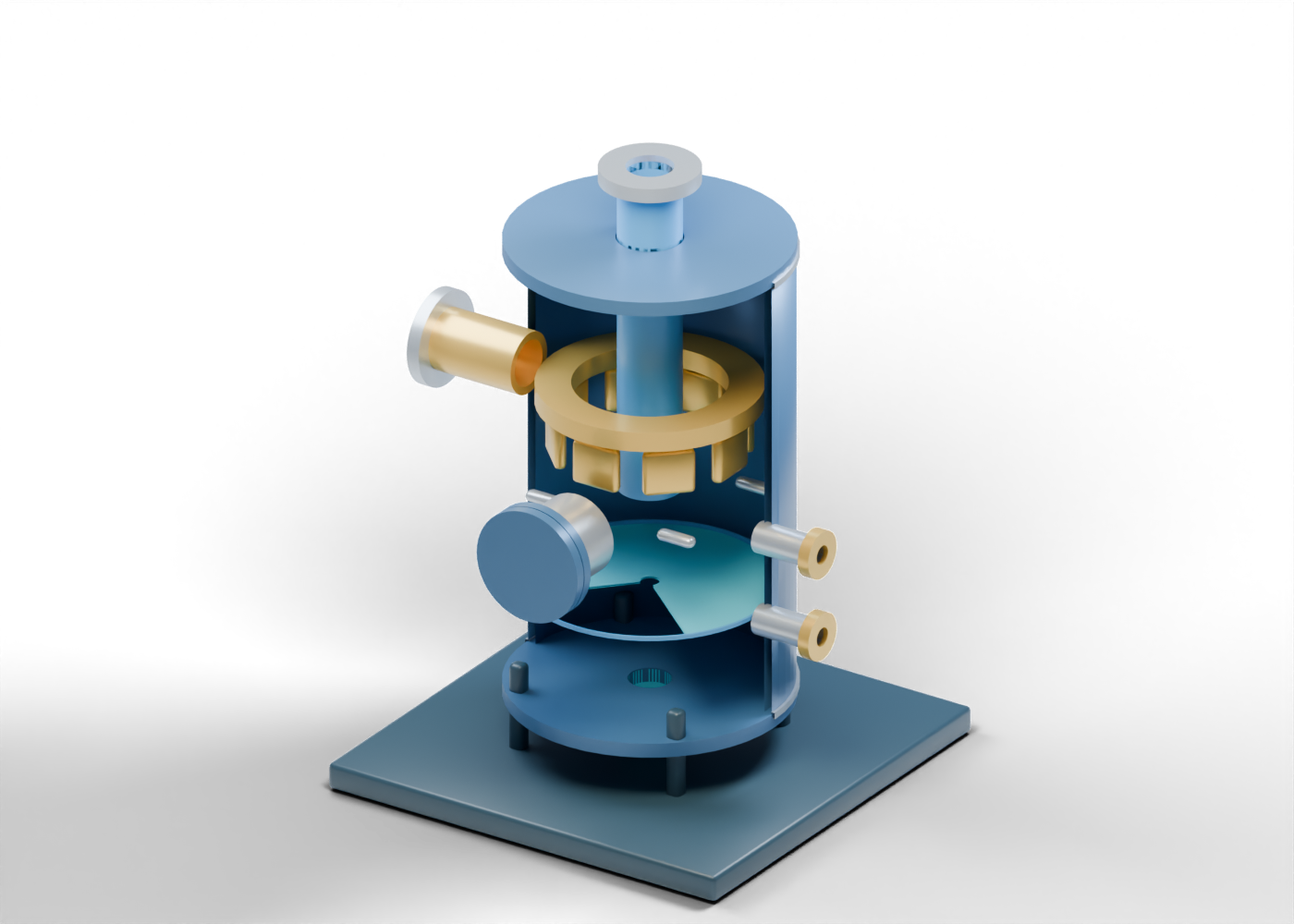
Begin at the open wet-steam inlet. It meets an actual bore in the hollow vessel wall. The browser asset retains the full wall; the poster exposes the inside only for viewing. There is no matched generator outlet pipe, valve train, pressure condition or water-quality record.
The open inlet-guide annulus and third individual guide blade are independent teaching shapes. Eight blades can be selected separately. Their spacing and angle are invented. This is not a manufacturer cyclone pack, specified inlet device or calculated liquid-removal method.
| Readable region | Teaching question | Result it cannot prove |
|---|---|---|
| Open wet-steam inlet | Where might the separator receive a stream? | Flow or inlet steam quality |
| Guide annulus and blades | Where could internal guiding be discussed? | Separation efficiency or pressure drop |
| Central riser and upper neck | Which boundary represents the steam side? | Injection-ready dryness |
| Blue lower plane | Where is an illustrative liquid region? | Actual level or volume |
| Lower neck | Which boundary represents liquid blowdown? | Flash, recovery or disposal route |
3. Locate the upper steam boundary
The central hollow steam riser has open inner and outer geometry, and the upper steam outlet neck passes a real top-closure opening. Select the upper outlet collar to see where this model ends. A clear bore is only a geometric fact. It supplies no steam dryness, pressure, temperature, line rating or suitable injection condition.
The separate SAGD well-pair lesson begins at an open injector boundary. It is useful for understanding where steam can be injected in the process story, but neither model designs the connection.
4. Keep liquid handling separate
The illustrative lower liquid surface is a partial blue plane at an arbitrary height. It is neither a sensor reading nor a separated-water result. The lower liquid blowdown neck passes an actual lower-closure bore and ends open at the blowdown outlet collar. Blowdown control, flashing, heat recovery, recycle, treatment and disposal are outside this drawing.
Two different drilled side locations, including the upper level boundary neck, mark where level connections might be discussed. No gauge, alarm, setpoint or control logic follows from their positions.
5. Read the enclosure and access carefully
The closed access cover is a separate solid piece before a real wall opening. It is a static closed pose, not an entry method or a statement about pressure isolation. The top closure and lower closure have real central openings for the two outlet roles. Neither closure is a pressure-vessel design.
Four support feet have geometric anchor locations. Their shape establishes no foundation, stress, attachment strength or safe-service rating. Original colour and proportions help distinguish paths; they are not an industry colour standard or a surveyed vessel.
6. Compare the three models without joining them
Open the complete separator model and trace its inlet, guide, riser, upper steam outlet, liquid marker and lower liquid outlet. Then compare the generator's open wet-steam outlet and well pair's injector boundary.
If a project report gives steam quality, blowdown, injection pressure or a water-recycling figure, check the dated, site-specific record and the definition behind that number. None of the three original scenes calculates or verifies plant performance.