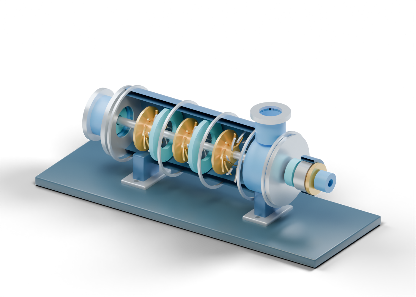
1. What the stages are for
Siemens Energy's compression white paper describes a centrifugal stage as a rotating impeller followed by stationary diffuser and, between stages, a return channel that prepares gas for the next stage. Our original three-stage explorer separates those roles into selectable parts. It is an invented static teaching model, not a particular compressor or a pressure and performance diagram.
The reciprocating-compressor lesson describes a different compression mechanism. Comparing the two helps clarify vocabulary; it does not identify which machine is right for a field, pipeline or plant.
2. Start with boundaries, not performance
The open axial suction neck and its bored flange identify an inlet boundary. The complete hollow casing wall encloses three stage groups and has a real upper opening beneath the open discharge neck. The browser begins with a reversible half-section of that wall. None of these openings proves a continuous, pressure-tight gas route through the internals.
Baker Hughes's pipeline-compressor overview describes suction and delivery nozzle, casing and between-end bearing roles in actual machines. We borrowed those roles, not its product geometry, number of impellers, sizes or operating values.
3. Find the rotating side of each stage
The gold stage-one impeller vane is one of eight invented swept strips around the common shaft. Separate second-stage and third-stage vanes let you compare three groups without confusing them with one large wheel. Each has its own hub and front/back shrouds. The studio still hides camera-facing shrouds and carriers after the complete model is exported so the vanes can be seen at article size.
Those static blade profiles supply no speed, aerodynamic efficiency, stage head, gas temperature, vibration or compressor map. The picture does not show a running rotor.
4. Separate diffusers and return guides
The silver first diffuser vane belongs to a stationary group outside the first impeller. The blue first return-guide vane marks an interstage role before the next group. The final stage has its own diffuser vane but no fourth-stage return guide. A final collector-location annulus is only a visible role marker, not a designed volute or a calculated path to the outlet.
| Visible cue in the original model | What needs actual equipment evidence |
|---|---|
| Three impeller groups with separate vanes | Rotor design, speed and aerodynamic performance |
| Diffuser and return-guide groups | Tested flow passage, losses and pressure recovery |
| Full casing and bored discharge | Pressure boundary, connection and containment |
| Static seal and bearing locations | Seal-gas, lube-oil and vibration systems |
| Upper outlet boundary | Selected discharge conditions and protection |
5. Look outside the gas path
A drive-end dry-gas-seal location is separate from the drive-side bearing enclosure and thrust-disc marker. Siemens Energy's dry-gas-seal overview distinguishes gas sealing from protection against bearing-oil ingress. Our annuli and pad cues have no seal faces, support-gas circuit, vent, lubricant, load capacity, emission result or maintenance instruction.
6. Connect the machine to a facility question
The independent suction-scrubber lesson and gas-compression-facility scene place compressor roles beside separation and cooling concepts. They are not matched packages, a P&ID or a safe operating sequence. Use the 121-part compressor explorer beside a real equipment record and ask for the selected machine, gas composition, performance map, surge-control basis, seal and bearing systems, casing data and field measurements before accepting a performance or safety claim.