1. Why treat an oil-and-water emulsion?
Produced oil can arrive with water that does not readily leave in an earlier free-water knockout. A heater treater is one upstream vessel type that can use heat to help treat the emulsion before oil and water move to separate handling. The US EPA SPCC guidance distinguishes a free-water knockout from a heater treater and describes the broad oil, water and gas separation role. The SLB treater glossary also describes heat as one possible aid to emulsion treatment. These sources establish concepts, not this vessel's design or performance.
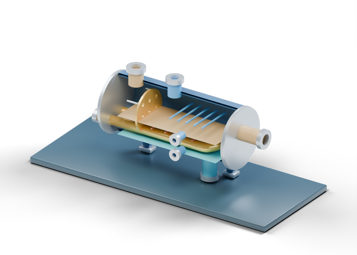
The interactive AlbertaOil heater-treater lesson is an original 46-part teaching scene. Its blue and prairie-gold poster removes the near shell half for a clear view; the browser model keeps the complete wall and its closed inspection cover. No operating plant, named product or engineering specification is represented.
2. Start at the feed and entry region
The emulsion feed reaches a real opening in the complete vessel wall. A nine-hole inlet marker sits inside. Those nine holes are real geometry, but the invented pattern does not predict flow distribution, emulsion breaking or separation. The model does not select an oil, water chemistry, flow rate or pressure.
3. See where heat could enter the story
The open U-shaped tube travels from two separate bores in the heating-side end closure and returns to its second open end. It is a location cue for a heat-transfer region, not a burner, fuel train, exhaust design or simulation. Kimray's heater-treater training explains the broad role of heating and controls in actual equipment; no product geometry or settings were copied into this model. Five open settling-region rails mark later space without specifying a coalescer, baffle or residence time.
| Scene element | Helps locate | Does not establish |
|---|---|---|
| Feed and nine-hole marker | Entry region | Selected emulsion or inlet performance |
| Open U-shaped tube | Possible heat region | Heat duty, burner or fuel safety |
| Open rails | Settling space | Coalescence or retention time |
| Blue and ochre planes | Separate reading regions | Measured levels or phase behaviour |
| Oil and water exits | Distinct destinations | Product quality or disposal approval |
4. Follow gas, oil and water separately
An upper gas boundary points to gas handling outside this scene. The higher oil exit passes through a separate bore in the far end closure. The lower produced-water draw points to further water handling. The blue water-region plane is deliberately static and arbitrary; it is not an interface measurement. The two side observation openings are uninstrumented locations without alarms or controls.
In a real project, each stream needs its own handling and measured acceptance criteria. Nothing in this illustration verifies the oil specification, water quality, gas composition or safe discharge.
5. Compare neighbouring vessel roles
The free-water knockout helps explain a prior unheated water-removal boundary. The three-phase separator highlights gas, oil and water outlets. The crude-oil desalter is a different refinery lesson involving wash water before distillation. These are separate educational models, not a proposed connected plant.
For a claim about a particular heater treater, ask for feed sampling, the heating and fuel basis, phase measurements, outlet specifications, vessel and controls documentation, and qualified technical review. A rendered component cannot supply that evidence.
6. Explore the complete model
Open the AlbertaOil heater-treater atlas page and select the feed, nine-hole entry marker, open U-shaped tube, higher oil exit, lower water draw and closed inspection cover. The model is an education aid; it is not a construction drawing, operating procedure or maintenance instruction.