1. What makes it a gear pump?
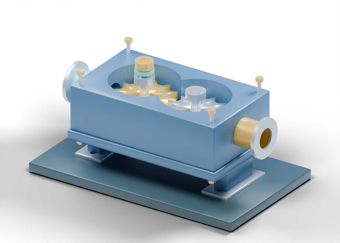
A gear pump is a rotary positive-displacement pump: two meshing gear wheels act as displacement and separating elements. That principle differs from the impeller and diffuser roles in our separate centrifugal-pump lesson. Open the original external-gear-pump explorer to compare the parts. Its proportions are invented; it is not a named oilfield product or an operating pump.
2. Separate the drive gear from the idler
The Parker fixed-displacement gear-pump catalogue describes a drive gear on a drive shaft and a second driven gear and shaft inside a housing. Our gold drive gear and silver idler gear are different selectable meshes. Each has twelve broad teeth and a real central bore. The drive shaft and idler shaft remain separately identifiable.
These frozen teeth are teaching silhouettes. Their profile, spacing and contact have not been designed as a correct involute mesh. Looking at them cannot establish torque transfer, rotation direction, displacement, leakage or a flow rate.
3. Look through the housing and both ports
The complete twin-cavity housing has two actual intersecting openings around the illustrated gears. A separate bored inlet neck and outlet neck meet drilled side passages. Parker's catalogue distinguishes the housing and inlet/outlet roles in a real gear-pump assembly. Here the open geometry helps locate boundaries; it does not prove that the invented gear and casing shapes form sealed, connected pumping pockets.
A real application would need a selected fluid, duty, port arrangement and system design. The browser's reveal control can hide the casing to make the gears easier to compare, while the original still shows the top cover lifted from view. Neither view is a cross-section of a particular manufacturer pump.
4. Covers, wear regions and shaft sealing
The interactive model retains a front cover with two shaft openings and a separate rear cover. A front wear-plate location and rear bearing-bush location point to questions about side clearance and shaft support. The drive-end seal location is another distinct region. Parker's document describes wear-plate, bearing and shaft-seal elements for its own pumps; our rings only identify possible roles. They provide no selected materials, loading, lubrication, seal arrangement or pressure containment.
| What the original model makes inspectable | What a real claim still needs |
|---|---|
| Two labelled twelve-tooth silhouettes | Correct gear profile, meshing and clearances |
| Bored twin cavity and side ports | Selected casing, porting and pressure integrity |
| Distinct drive and idler shafts | Loads, bearings, coupling and guarded driver |
| Wear-plate and bush locations | Material, lubrication and leakage evidence |
| Cover holes and seal location | Closure design, sealing and tested duty |
5. Compare pump families without treating them as interchangeable
The separate multistage centrifugal-pump explorer labels impellers, diffusers and return guides; the progressing-cavity-pump explorer labels a different rotor/stator concept. Those independent original models help compare vocabulary. They are not matched equipment selections for one Alberta facility, and none supplies performance curves or a safe substitution decision.
6. Turn the component map into better questions
Use the 38-part gear-pump explorer to find a gear, port, shaft and cover. Then ask for the named pump's drawings, specified fluid and operating range, pressure protection, material/clearance choices, acceptance records and qualified review before accepting a real performance or safety statement. A clear 3D model can organize those questions. It cannot serve as a fabrication, selection, maintenance or operating instruction.